Myford ML7 Cross Slide Leadscrew Thrust Bearing Modification
This is a simple modification to the Myford ML7 which will:
- Eliminate any backlash between the cross slide and the leadscrew.
- Eliminate wear in the cross slide end plate.
- Reduce operational friction.
Materials required:
- 2x NTA411 1/4"x11/16"x0.1401" Needle Roller Thrust Bearings.
- 1x R168ZZ 1/4"x3/8"x1/8" Single Row Ball Bearing.
The bearings can be ordered as a set (Here) but before ordering, please check the end of your leadscrew where the bearings fit is actually 0.25". Please note that this modification does not work on the Myford Super 7 lathe.
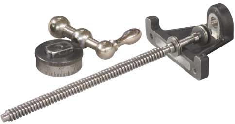
The drawing MYF001 shows the work to be carried out on the cross slide end plate.
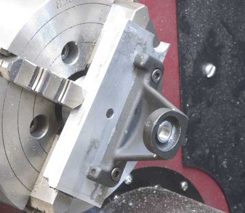
The photo shows a simple set-up on the lathe for boring out the hole and turning the front face. The actual dimensions may vary for your machine but the objective is to turn the front face so there is sufficient clearance between the dial and end plate with the thrust bearing sandwiched between the two.
The rear face can be reduced with a 3/4" spot face cutter or milled. Again, the dimension is not critical so long as there is enough (and not too much!) thread left on the leadscrew to securely lock the ball handle in place.
Arc Euro Trade Ltd has taken all reasonable care to ensure that the "Projects" pages published here were accurate on the date of publication. Arc Euro Trade Ltd takes no responsibility for the consequences of error or for any loss or damage suffered by users of any of the information published on any of these pages, and such information does not form any basis of a contract with readers or users of it.
Copyright © 2014, Arc Euro Trade Ltd. All Rights Reserved.
Copyright © 2014, Arc Euro Trade Ltd. All Rights Reserved.